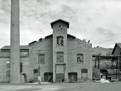
The reverberatorory furnaces were not sufficiently efficient
to extract all the copper from the ore, with the resulting slag contained as
much 18 percent .copper. In order to remove this copper, the slag was further refined
in a second furnace more fitted for such work known as a cupola furnace. Not
surprisingly, this second furnace was located in a structure known as the
cupola building, shown here in a 1972 HABS photograph:
Using the above photograph and some measurements I took at the Quincy Smelter about thirty years ago when I first considered modeling it,I created a set of scale plans from which to build the model, the front elevation of which is shown below.
Rather than jumping into the job of wall construction, which I expected would take three or four days, I decided to take a little side trip before calling it a day. Referring to the HABS photo above, you will see the central door into the elevator was outfitted with a door which opened vertically with the aid of a counterweight which can be seen hanging to the right of the door track. It was this little detail which decided to recre first.
I first looked through my parts stash for something which could serve to replicate the two pulleys on the head frame of the door track. Coming up empty-handed, I decided to scratch build the two pulleys using 1/8" and 1/16" disks cut from sheet styrene using hole punches, shown below along with the scrap styrene from which they were cut and a razor blade to provide some sense of scale.
Gluing the pulleys together was somewhat of a pain. First, a 1/8" disks was placed on the work surface. One of the 1/16" disks was then picked up by lightly spearing it on the center of one side with the sharp point of the Xacto knife, a drop of solvent applied to its back side and then the smaller disk carefully placed at the center of the larger disk and held in place until the solvent set, as shown below. A second 1/16" disk was then added, and finally a second 1/8" disk applied atop the stack, building up the pulleys.
With the pulleys fabricated, I then set about building the upper framework to house them, using some extremely small nul/bolt/washer moldings to indicate the bearing centers for the pulleys and the points at which the head frame was bolted to the vertical slides. Here we see the completed front half of this upper head frame along with a penny to give an idea of scale. After finishing the rest of the framwwork, I realized it was late, and I headed for bed.


No comments:
Post a Comment